 EN
EN

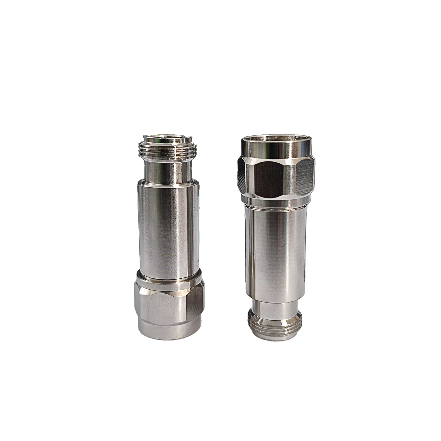
Calculating Power Ratings and Thermal Load Requirements
When radio frequency engineers and laboratory test technicians design signal conditioning pathways, selecting the correct hardware component begins with a rigorous evaluation of power handling capacities. Implementing a coaxial attenuator within high power transmitters or measurement test benches requires a calculation of incoming signal wattage and anticipated thermal dissipation loads. Microwave design consultants emphasize that choosing an attenuator with appropriate power ratings helps prevent internal resistor degradation and unexpected network interruptions. Drawing from years of field observations across wireless infrastructure deployments, technical specialists note that verifying continuous wave and peak power thresholds beforehand protects downstream instruments from overloads and ensures stable system operation across project sites.
Verifying Frequency Bandwidth and Insertion Loss Compatibility
Signal conditioning components possess physical and electrical boundaries regarding the operational frequency spectrum they can handle without signal distortion. A reliable coaxial attenuator must be selected to match the bandwidth requirements of the transmission system, whether operating at lower VHF frequencies or extending into multi gigahertz microwave ranges. RF testing authorities point out that deploying an unverified component outside its designated frequency band can cause attenuation flatness variations and increased insertion loss. Reviewing manufacturer data sheets and electrical compliance parameters ensures that the device maintains consistent signal reduction across the operating frequency spectrum without compromising transmission fidelity.
Ensuring Precise Impedance Matching and VSWR Control
Maintaining characteristic impedance matching is vital for preventing signal reflections, standing wave anomalies, and power loss within coaxial transmission lines. When integrating a coaxial attenuator into a circuit, technicians must confirm that the internal characteristic impedance of the device matches surrounding cabling, typically fifty ohms for data systems. Electrical engineering experts stress that mismatch between connector interfaces and the attenuator body creates voltage standing wave ratio spikes that affect data integrity. Verifying proper impedance alignment guarantees smooth power transfer and minimizes unwanted signal reflections during operation in electronic setups.
Following Physical Installation and Connection Best Practices
The physical installation phase of hardware deployment requires attention to mechanical mating techniques to prevent premature wear or thread damage. Properly securing a coaxial attenuator involves using calibrated torque wrenches to achieve coupling pressure without stripping precision external threads or deforming internal contact pins. Facilities management specialists highlight that relieving physical cable tension and mounting heavy inline components securely to chassis brackets prevents lateral pulling forces from introducing micro gaps. Adhering to mechanical integration protocols safeguards hardware against environmental stress and maintains continuous ground plane contact across test benches and industrial installations.
Partnering with Established Manufacturing and Supply Chain Leaders
Sourcing high frequency signal conditioning hardware depends on collaborating with seasoned manufacturing partners who understand the demands of microwave engineering. Partnering with an experienced production source ensures that every precision component meets international quality standards and regulatory benchmarks. By leveraging the advanced engineering capabilities, quality control protocols, and supply chain expertise of industry pioneers associated with AXRFCONNECTOR, hardware developers and telecom operators can acquire a dependable coaxial attenuator solution that supports long term success worldwide.