 EN
EN

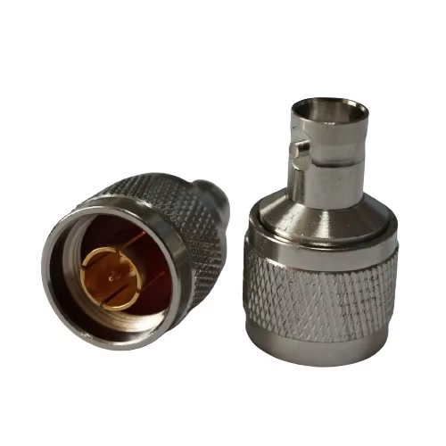
Solving Connector Incompatibility Across RF Systems
Whenever different RF equipment from varied domains—broadcast, flight, and defense testing—must interconnect, built-in connector formats frequently clash. BNC adapters bridge this gap by seamlessly connecting bayonet-spin (BNC) interfaces with common threaded counterparts (N, TNC, SMA), ensuring uninterrupted signal flow across mixed-connector environments.
Bridging BNC with N, TNC, and SMA RF interfaces in mixed-connector environments
Adapters certified for operation up to 18 GHz overcome impedance barriers while preserving signal fidelity—enabling direct connection between a video camera’s SMA output and a portable spectrum analyzer’s BNC input, or consolidating multiple defense instrument feeds onto a server chassis with predominantly BNC or SMA ports. These adapters maintain a consistent VSWR ceiling of 1.23:1 across their rated bandwidth, verified through standardized electronic technician testing. This performance ensures minimal insertion loss and stable impedance transition at every interface.
Mechanical mismatch: mating cycles, torque sensitivity, and contact resistance risks
Mechanical compatibility is as critical as electrical performance. Certified adapters withstand at least 300 mating cycles without degradation, maintaining contact resistance below 10 mΩ—key to near-lossless signal transfer. Torque application matters: hand-tightening suffices for most BNC connections, while N and TNC types require calibrated wrench torque per IEC 61169 standards to avoid over-compression or under-engagement. Axial and radial tensioning designs ensure stable coupling under vibration or thermal cycling. Strain relief is non-negotiable—especially in field-portable test stations subject to repeated deployment—and must be integrated into the adapter housing or cable assembly per MIL-STD-202G requirements.
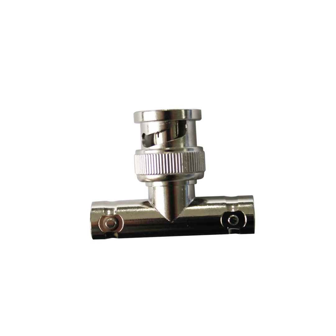
Ensuring Signal Integrity Through Impedance-Matched BNC to RF Adapters
50 Ω vs. 75 Ω impedance matching: minimizing VSWR, reflection loss, and signal distortion
Impedance matching is foundational to RF signal integrity. Most test and telecom gear operates at 50 Ω, while broadcast and video systems use 75 Ω. Mismatched connections cause signal reflections that elevate VSWR, increase insertion loss, and distort waveforms—potentially reflecting up to 4% of power even at low frequencies, with worsening effects above 1 GHz. A properly engineered BNC to RF adapter maintains a continuous, matched transmission path, holding VSWR below 1.2:1 and return loss above 20 dB across its operating range. This consistency prevents standing waves, preserves amplitude accuracy, and reduces noise floor elevation—critical for precision measurement and compliance validation.
Real-world impact: video broadcast (75 Ω) to lab test gear (50 Ω) interoperability
Field engineers routinely connect 75 Ω broadcast sources—such as HD-SDI cameras or satellite downlinks—to 50 Ω lab instruments like spectrum analyzers or oscilloscopes. Without an impedance-matched adapter, mismatches manifest as overshoot, ringing, and timing jitter—degrading picture quality and invalidating measurements. A high-fidelity BNC-to-RF adapter resolves this at the interface point, enabling reliable troubleshooting, EMI diagnostics, and regulatory testing without signal repeaters or system-level redesigns. This interoperability directly supports rapid deployment in mobile broadcast trucks, aerospace ground stations, and defense electronics integration labs.
Balancing Performance Trade-Offs in BNC to RF Adapter Design
Shielding Effectiveness and Transfer Impedance: Bayonet vs. Threaded RF Adapter Trade-Offs
BNC’s bayonet coupling offers speed and convenience—ideal for broadcast patch bays or telemetry setups—but exhibits higher transfer impedance than threaded alternatives. Above 4 GHz, shielding effectiveness can drop by ~47 dB due to minor gaps inherent in the quick-lock mechanism. In contrast, SMA and TNC adapters deliver superior EMI suppression and stable <0.5 dB insertion loss variation after 500 mating cycles, thanks to consistent contact pressure and tighter mechanical tolerances. When adjacent circuit sensitivity exceeds –90 dBm—as in sensitive receiver front-ends or low-noise amplifier chains—engineers should specify mil-spec grounding sleeves and prioritize threaded interfaces, especially when integrating legacy sensors with modern spectrum analyzers.
Material Quality, Plating, and Mechanical Stability’s Effect on Long-Term RF Reliability
Long-term reliability hinges on material science and precision plating. Surface roughness under 16 μin RA and ≥50 μin gold plating minimize wear-induced impedance drift in high-cycle applications like automated production test jigs. Zinc alloy connectors show measurable resonance shift (<220 MHz/year) under accelerated aging per EIA-364-41; stainless steel or brass cores with nickel underplating extend mean time between failure beyond 100,000 cycles while controlling cost. Torque retention below 1.3 in-lb prevents dielectric compression failures observed in 5G repeater deployments. Crucially, coefficient of thermal expansion (CTE) alignment between conductive and insulating materials is rigorously evaluated during custom adapter development—ensuring stability across operational extremes from –55°C to 125°C.
Frequently Asked Questions
What is the purpose of BNC adapters in RF systems?
BNC adapters are used to connect incompatible RF connectors, such as bayonet-spin (BNC) interfaces with threaded types like N, TNC, and SMA, ensuring seamless signal flow in mixed-connector environments.
How do BNC adapters maintain signal integrity?
BNC adapters are designed to manage impedance mismatches, maintain a low VSWR, and ensure minimal insertion loss, preserving signal integrity and allowing for accurate measurements.
What role does mechanical compatibility play in RF adapter efficiency?
Mechanical compatibility ensures durability through mating cycles, appropriate torque application, and stable connections under physical stress, which are crucial for effective signal transfer in RF systems.