 EN
EN

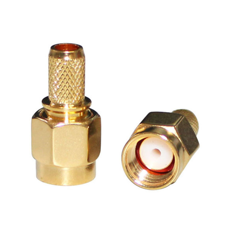
المواصفات الفنية الأساسية لمُوصِلات SMA RF الحديثة
نطاق التردد، المقاومة الكهربائية 50 أوم، وقدرة التحمّل الكهربائية في بيئات 5G-A وWi-Fi 7
حديث موصلات RF من نوع SMA تعمل بكفاءة من التيار المستمر حتى 18 جيجاهرتز، مع إصدارات دقيقة تصل إلى 40 جيجاهرتز—وتغطي بذلك بالكامل نطاق الترددات دون 6 جيجاهرتز ونطاق الترددات المتوسطة الذي يكتسب أهمية حاسمة في نشر تقنيات الجيل الخامس المتقدّم (5G-A) وواي فاي 7. ويضمن امتلاكها مقاومة معيارية قدرها 50 أوم انعكاسًا إشاريًّا ضئيلًا ونسبة موجة واقفة من الجهد (VSWR) منخفضة، ما يدعم مباشرةً سلامة الإشارة في البيئات التي تتطلب معدلات نقل بيانات عالية وزمن انتقال منخفض. وتتراوح القدرة على تحمل القدرة الكهربائية بين 50 واط و500 واط حسب التصميم، حيث تُعد الإصدارات ذات التصنيف الأعلى ضرورية للبنية التحتية الخلوية ونقاط الوصول لشبكات الواي فاي عالية الكثافة. وفي هذه التطبيقات، يُعتبر إدارة الحرارة أمرًا لا غنى عنه: فالتبديد المستمر للطاقة دون تبديد كافٍ للحرارة يؤدي إلى تسارع تدهور التوصيلات وانحراف المقاومة. ولذلك يجب على المهندسين إعطاء الأولوية لاختيار الموصلات استنادًا إلى في نفس الوقت التردد والقدرة والمتطلبات الحرارية—وليس كلٌّ منها بمعزل عن الآخر.
علم المواد: تلامس مطلية بالذهب، واستقرار العازل المصنوع من مادة البوليترافلوروإيثيلين (PTFE)، وسلامة نابض البريليوم النحاسي
تُحدد خيارات المواد الموثوقية طويلة الأمد والاتساق الكهربائي. وتوفّر نقاط التوصيل المركزية المطلية بالذهب (بسمك يتراوح بين ٠٫٥ و٢٫٥ ميكرومتر) مقاومة تلامس مستقرة تقل عن ١٠ ملي أوم، مع مقاومة الأكسدة والتآكل—وهو أمرٌ جوهري للحفاظ على فقد الإدخال (Insertion Loss) أثناء عمليات الاتصال المتكررة. أما القلب العازل، الذي يتكوّن عادةً من مادة البوليتيترا فلورو إيثيلين (PTFE)، فيحافظ على ثبات نسبي مرتفع للسماحية النسبية (εᵣ ≈ ٢٫١) عبر نطاق درجات الحرارة من –٦٥°م إلى +١٦٥°م، ما يمنع تغير المعاوقة الذي قد يؤدي إلى تشويه الإشارات العريضة النطاق. وتوفّر عناصر النابض المصنوعة من نحاس البريليوم مرونة ميكانيكية عالية: أكثر من ١٠٠٬٠٠٠ دورة اتصال مع قوة تلامس ثابتة تتراوح بين ٠٫٥ و١٫٥ نيوتن، مما يجعلها مثالية للتطبيقات الحساسة للاهتزاز مثل أنظمة الرادار automotive وأنظمة الفضاء الجوي. وبمجملها، تضمن هذه المواد أن تحتفظ موصلات SMA للترددات اللاسلكية (RF) بأداء الترددات اللاسلكية والسلامة الميكانيكية في البيئات التي تكون فيها الإجهادات البيئية والمتانة التشغيلية عوامل حاسمة في نجاح المهمة.
SMA مقابل RP-SMA: اعتبارات حرجة تتعلق بالتوافق والتركيب
عكس ترتيب دبابيس التوصيل ومخاطر عدم التوافق في العالم الحقيقي
موصلات SMA وRP-SMA غير متوافقة ميكانيكيًّا بسبب عكس التعيينات الجنسية: فموصل SMA القياسي يستخدم دبوسًا مركزيًّا ذكريًّا مع خيوط أنثوية، بينما يعكس موصل RP-SMA كلا العنصرين — أي دبوسًا مركزيًّا أنثويًّا مع خيوط ذكرية. ويُشكِّل هذا الانعكاس مخاطر جسيمة على التوافق التشغيلي في عمليات النشر الكثيفة لتقنيات 5G-A وWi-Fi 7. أما إجبار الموصلات على الالتحام فيؤدي إلى إجهاد ميكانيكي قد يُحدث شقوقًا في عازل البوليمر الفلوريني (PTFE)، ما يرفع معامل الاستهلاك الموجي الراجع (VSWR) بنسبة تصل إلى ٤٠٪ ويُفاقم فقدان الانعكاس (Return Loss) بما يتجاوز الحدود المحددة. كما أن الاتصال الخاطئ بين أجهزة الاختبار والهوائيات — حتى لو كان لفترة قصيرة — قد يتسبب في انعكاس إشارة يزيد عن ٣ ديسيبل، مما يؤثر تأثيرًا بالغًا على مقدار الانحراف المتجهي للخطأ (EVM) في أنظمة Wi-Fi 7، حيث تكون الهوامش المسموح بها أضيق من ±٣٪. ولذلك يجب دائمًا التأكد من نوع الموصل عبر الرسم التخطيطي أو الفحص المادي قبل التكامل؛ إذ يمنع التحقق البصري حدوث أضرار لا رجعة فيها في المسارات الإشارية الراديوية.
تحديد الجنس، مواصفات العزم (٧–١٠ بوصة-رطل)، وأفضل الممارسات لمنع التلف
يُعَدُّ التعرُّف الصحيح على النوع (الذكوري أو الأنثوي) أساسياً: فالاتصال المركزي البارز يدلُّ على النوع الذكوري، بينما يدلُّ الانخفاض في المركز على النوع الأنثوي. ويؤكِّد موضع الخيط أيضاً ذلك التمييز—فالخيوط الخارجية تدلُّ على الأجزاء الذكرية، والخيوط الداخلية تدلُّ على الأجزاء الأنثوية. ويجب التحكُّم بدقة في عزم الدوران أثناء التوصيل ضمن النطاق ٧–١٠ إنش-رطل باستخدام أدوات معايرة دقيقة: فتجاوز عزم الدوران ١٠ إنش-رطل يؤدي إلى تشويه دائم لزنبركات البريليوم النحاسية، بينما يؤدي عزم الدوران الأقل من ٧ إنش-رطل إلى اتصال متقطِّع—وخاصةً تحت تأثير الاهتزاز في وحدات الرادار السيارات. واتبع هذه الممارسات المُثبتة ميدانياً:
- الفحص قبل التوصيل : استخدم تكبيراً بمعامل ١٠× للكشف عن أي شوائب أو تلف في نقاط الاتصال
- محاذاة الخيوط : قم بالتدوير عكس اتجاه عقارب الساعة حتى تلتحم الخيوط مع سماع صوت «نقرة» مسموعة قبل الشدِّ النهائي
-
التحقق بعد التركيب : تحقَّق من فقد الإدخال (<٠٫١ ديسيبل) وفقد الانعكاس باستخدام ماسح محلِّل الشبكة المتجه (VNA)
تُظهر البيانات الميدانية المستخلصة من عمليات تركيب محطات القاعدة أن الالتزام ببروتوكولات العزم المناسبة يضاعف عمر خدمة موصلات SMA للترددات اللاسلكية ثلاث مرات مقارنةً بالتركيب غير الخاضع للرقابة.
مشهد التطبيقات لعام ٢٠٢٦: حيث تتفوق موصلات SMA RF
الدور المستمر في بنية تحتية ٥G-A، ونقاط وصول Wi-Fi ٧، ووحدات الرادار automotive
ورغم ظهور بدائل ناشئة، تظل موصلات SMA RF لا غنى عنها في ثلاث مجالات تطبيقية عالية النمو عام ٢٠٢٦. ففي بنية تحتية الجيل الخامس المُحسَّن (5G-A)، تُستخدم هذه الموصلات كوسيلة اتصال رئيسية بين وحدات الإرسال والاستقبال والهوائيات في محطات القاعدة ووحدات الإرسال اللاسلكية البعيدة—مقدِّمةً مقاومةً ثابتةً قدرها ٥٠ أوم وخسارة إدخال منخفضة عبر نطاق التردد السائد من ١ إلى ٦ جيجاهرتز. أما في نقاط وصول واي-فاي ٧ (Wi-Fi 7)، فإن الاتصال الحلزوني لموصلات SMA يوفِّر استقرارًا ميكانيكيًّا متفوقًا مقارنةً بالبدائل ذات الاتصال الدافع (Push-on)، مما يضمن اتصالاتٍ موثوقةً في البيئات المؤسسية والصناعية الخاضعة لتقلبات الحرارة والاهتزاز. ويغطي نطاق ترددها البالغ ١٨ جيجاهرتز جميع قنوات واي-فاي ٧ (٢,٤ و٥ و٦ جيجاهرتز) بسهولة، مع الالتزام بمواصفات صارمة لخسارة الانعكاس (>٢٠ ديسيبل). وفي رادارات السيارات، تُستخدم موصلات SMA على نطاق واسع في تركيبات الاختبار والواجهات المساعدة للمستشعرات الخاصة بوحدات الرادار قصيرة المدى العاملة عند تردد ٢٤ جيجاهرتز—مستفيدةً من قوة التوصيل المتكررة، ومتانة التلامس المطلّى بالذهب، والقابلية البينية الجاهزة للإنتاج. ووفقًا لتحليل سوقي أجرته شركة LightCounting ونُشِر في عام ٢٠٢٥، شكلت موصلات SMA ما نسبته ٢٢,٦٪ من حصة السوق العالمية لموصلات الترددات الراديوية، ما يؤكد استمرار أهميتها حيث تفوق الأداء المثبت، ونضج سلسلة التوريد، والتوافق بين المورِّدين أي مكاسب هامشية قد تقدمها أشكال جديدة. ويختار المصممون موصلات SMA ليس باعتبارها حلًّا تقليديًّا تنازليًّا، بل باعتبارها حلاًّ مُصمَّمًا خصيصًا يوازن بين تغطية الترددات، والمتانة الميكانيكية، ودعم النظام البيئي في الشبكات التي توسَّع بسرعة.
الأسئلة الشائعة
ما هو نطاق التردد الذي تدعمه موصلات SMA للترددات الراديوية؟
تعمل موصلات SMA للترددات الراديوية بكفاءة من التيار المستمر (DC) حتى 18 جيجاهرتز، مع إصدارات دقيقة تمتد إلى 40 جيجاهرتز.
لماذا تُعد علوم المواد مهمةً لموصلات SMA للترددات الراديوية؟
تضمن علوم المواد الموثوقية الطويلة الأمد والثبات الكهربائي. وتوفّر ميزات مثل التلامس المطلي بالذهب، ونوى العازل المصنوعة من مادة البوليترافلوروإيثيلين (PTFE)، و النوابض المصنوعة من نحاس البريليوم أداءً مستقرًا في ظل ظروف متنوعة.
ما الفروق بين موصلات SMA وموصلات RP-SMA؟
يتمثل الفرق الجوهري في تكوين الدبوس المركزي: فموصلات SMA تستخدم دبوسًا مركزيًّا ذكريًّا وخرائط أنثوية، بينما تُعاكس موصلات RP-SMA تعيين الجنس. وقد يؤدي هذا عدم التوافق إلى مشكلات في الأداء عند تركيبها بشكل غير صحيح.
ما مواصفات العزم الموصى بها لموصلات SMA للترددات الراديوية؟
يجب التحكم في عزم التوصيل ضمن النطاق من 7 إلى 10 بوصة-رطل باستخدام أدوات معايرة لمنع التلف أو حدوث مشكلات في التوصيل المتقطع.