 EN
EN

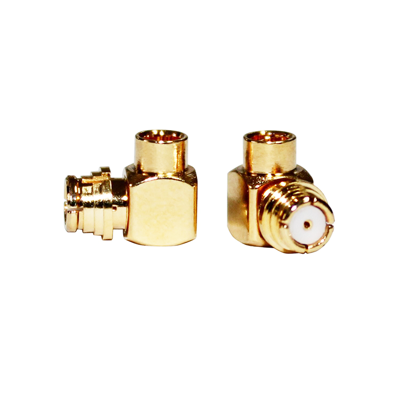
Electrical Performance Fundamentals of SMA RF Connectors
50‑Ω impedance control and sub‑1.20 VSWR: Ensuring signal integrity from DC to 6 GHz
An SMA RF connector must maintain a precise 50‑Ω characteristic impedance across its entire operating band to minimize reflections and preserve signal integrity. Impedance deviations cause incident power to reflect toward the source, increasing the Voltage Standing Wave Ratio (VSWR). For reliable performance from DC to 6 GHz, manufacturers target a VSWR below 1.20—corresponding to a return loss better than −20 dB and indicating that over 99% of forward power reaches the load. Achieving this requires tight dimensional control of the center conductor diameter, dielectric spacing, and outer conductor geometry. Even minor manufacturing variations can elevate VSWR and compromise performance in sensitive test, communication, or radar systems.
Insertion loss ≤0.15 dB at 6 GHz and frequency limitations beyond 18 GHz due to second‑mode resonance
Low insertion loss is essential for preserving signal amplitude. A high-quality SMA RF connector typically exhibits ≤0.15 dB insertion loss at 6 GHz—enabled by high-conductivity materials like gold-plated beryllium copper and low-loss PTFE dielectrics. However, above 18 GHz, the connector’s dielectric support bead begins to excite a second-mode resonance. Because the bead’s physical dimensions become comparable to a half-wavelength at these frequencies, this resonance sharply degrades both insertion loss and VSWR. As a result, standard SMA connectors are not suitable for millimeter-wave applications. Engineers should transition to precision alternatives such as 3.5 mm or 2.92 mm connectors when operating beyond 18 GHz.
Mechanical Precision Directly Governs RF Performance
±0.025 mm center conductor alignment tolerance and its effect on reflection coefficient stability
The center conductor in an SMA RF connector must be aligned within ±0.025 mm of the true axis. This tolerance directly governs reflection coefficient (S₁₁) stability by minimizing impedance discontinuities at the mating interface. A misalignment of just 0.05 mm can raise VSWR from 1.05 to >1.20 at 6 GHz—degrading return loss by several decibels. Consistent alignment ensures stable 50‑Ω impedance across the full DC-to-6 GHz band. Manufacturers achieve this through advanced injection-molding process control, monitoring melt flow, cooling rate, and mold cavity pressure in real time. The result is repeatable geometry with reflection coefficient variation under 0.01 across production lots—critical for radar, military communications, and high-fidelity test equipment.
Dielectric bead geometry (e.g., 2.92 mm PTFE) and resonance shift implications for broadband consistency
The dielectric bead—typically made of PTFE or a PTFE-based composite—centers the inner conductor and enables a controlled impedance transition. Its dimensions, such as the 2.92 mm diameter common in precision SMA designs, must be held to micron-level tolerances. Deviations shift the electrical length of the junction, introducing resonant dips in the VSWR curve that narrow usable bandwidth. In broadband applications like cellular backhaul or satellite links, such shifts can increase insertion loss by ≥0.05 dB near 12 GHz. Tight control of bead geometry ensures flat broadband performance from DC to 18 GHz while preventing second-mode resonance from encroaching into the operational band.
Standards Compliance: The Non-Negotiable Foundation for SMA RF Connector Reliability
Adherence to international standards—including MIL-STD-348 and IEC 61169-35—is foundational to SMA RF connector reliability. These specifications define strict requirements for dimensional tolerances, material properties, and electrical behavior, ensuring consistent 50‑Ω impedance control, low VSWR, and minimal signal degradation across the rated bandwidth. Standardized interfaces guarantee interoperability between components from different vendors, reducing integration risk. Certified testing under these standards validates key performance claims—including insertion loss and phase stability—making compliance essential for mission-critical applications such as radar systems and high-frequency test instrumentation up to 18 GHz.
PCB Integration Best Practices for Optimal SMA RF Connector Performance
Controlled-depth via stubs and 50‑Ω microstrip launches to suppress discontinuity-induced VSWR spikes
To preserve the SMA connector’s low VSWR, the transition from its center pin to the PCB trace must be electromagnetically seamless. Through-hole via stubs introduce impedance discontinuities that reflect energy and spike VSWR above 1.20:1. Controlled-depth vias eliminate unused barrel length, reducing capacitive loading. Pair this with a precisely tuned 50‑Ω microstrip launch that matches the connector’s characteristic impedance—and maintain a continuous reference plane beneath the pad. Together, these practices keep reflection coefficients below 0.10, safeguarding signal integrity from DC to 6 GHz.
Rogers RO4350B vs. FR4: Material selection impact on dispersion, loss tangent, and impedance stability above 3 GHz
Above 3 GHz, FR4’s high loss tangent (~0.025) and variable dielectric constant (εᵣ ≈ 4.2–4.8) induce dispersion and impedance drift, undermining the SMA connector’s phase and amplitude fidelity. In contrast, Rogers RO4350B offers a stable εᵣ of 3.48 ± 0.05 and a low loss tangent of 0.003—along with minimal moisture absorption—ensuring consistent impedance and reduced long-term drift. For designs operating above 3 GHz, switching from FR4 to RO4350B reduces insertion loss variation by more than 0.2 dB per inch, allowing the SMA connector to deliver its rated RF performance without board-level compromise.
Ready to Deploy Precision SMA Connectors for Your RF Systems?
SMA RF connectors are the critical backbone of all electronic systems—substandard connectors with poor precision can cause signal degradation, unexpected downtime, and costly field recalls that damage your brand reputation and erode customer trust. By choosing precision-engineered SMA connectors manufactured to the tightest industry tolerances, you’ll unlock consistent signal integrity, reliable system performance, and faster time-to-market for your products.
For industrial-grade SMA RF connectors and custom cable assemblies tailored to your exact OEM requirements, partner with Zhenjiang Aoxun Electronic—your trusted RF manufacturing partner with 30+ years of specialized industry experience. We hold ISO 9001 and RoHS certifications, operate a 5,000+ square meter factory equipped with 60+ state-of-the-art CNC lathes, and deliver up to 60,000 units daily with first-pass yields exceeding 98.5%. Our comprehensive one-stop services include design consultation, connector selection optimization, custom prototyping, and global shipping. Contact us today for a no-obligation engineering consultation or free custom sample to optimize your next RF project.
FAQ
Q: What is the importance of 50‑Ω impedance in SMA RF connectors?
A: Maintaining a precise 50‑Ω impedance is crucial for minimizing reflections and preserving signal integrity throughout the operating frequency range.
Q: Why is VSWR below 1.20 essential for SMA RF connectors?
A: A VSWR below 1.20 ensures minimal return loss, allowing over 99% of forward power to reach the load, which is vital for reliable performance.
Q: Why do standard SMA connectors face limitations beyond 18 GHz?
A: Above 18 GHz, the dielectric bead excites a second-mode resonance due to its comparable dimensions to a half-wavelength, degrading insertion loss and VSWR.
Q: How does dielectric bead geometry impact SMA RF connector performance?
A: Precise bead geometry ensures consistent impedance and avoids resonant dips that can narrow the usable bandwidth.
Q: Why is compliance with standards like MIL-STD-348 essential for SMA RF connectors?
A: Standards define strict requirements ensuring consistent performance, interoperability, and reliability in mission-critical applications.
Q: What PCB materials are recommended for applications above 3 GHz?
A: Rogers RO4350B is recommended due to its stable dielectric constant, low loss tangent, and minimal moisture absorption, providing superior performance over FR4.
Table of Contents
- Electrical Performance Fundamentals of SMA RF Connectors
- Mechanical Precision Directly Governs RF Performance
- Standards Compliance: The Non-Negotiable Foundation for SMA RF Connector Reliability
- PCB Integration Best Practices for Optimal SMA RF Connector Performance
- Ready to Deploy Precision SMA Connectors for Your RF Systems?
- FAQ