 EN
EN

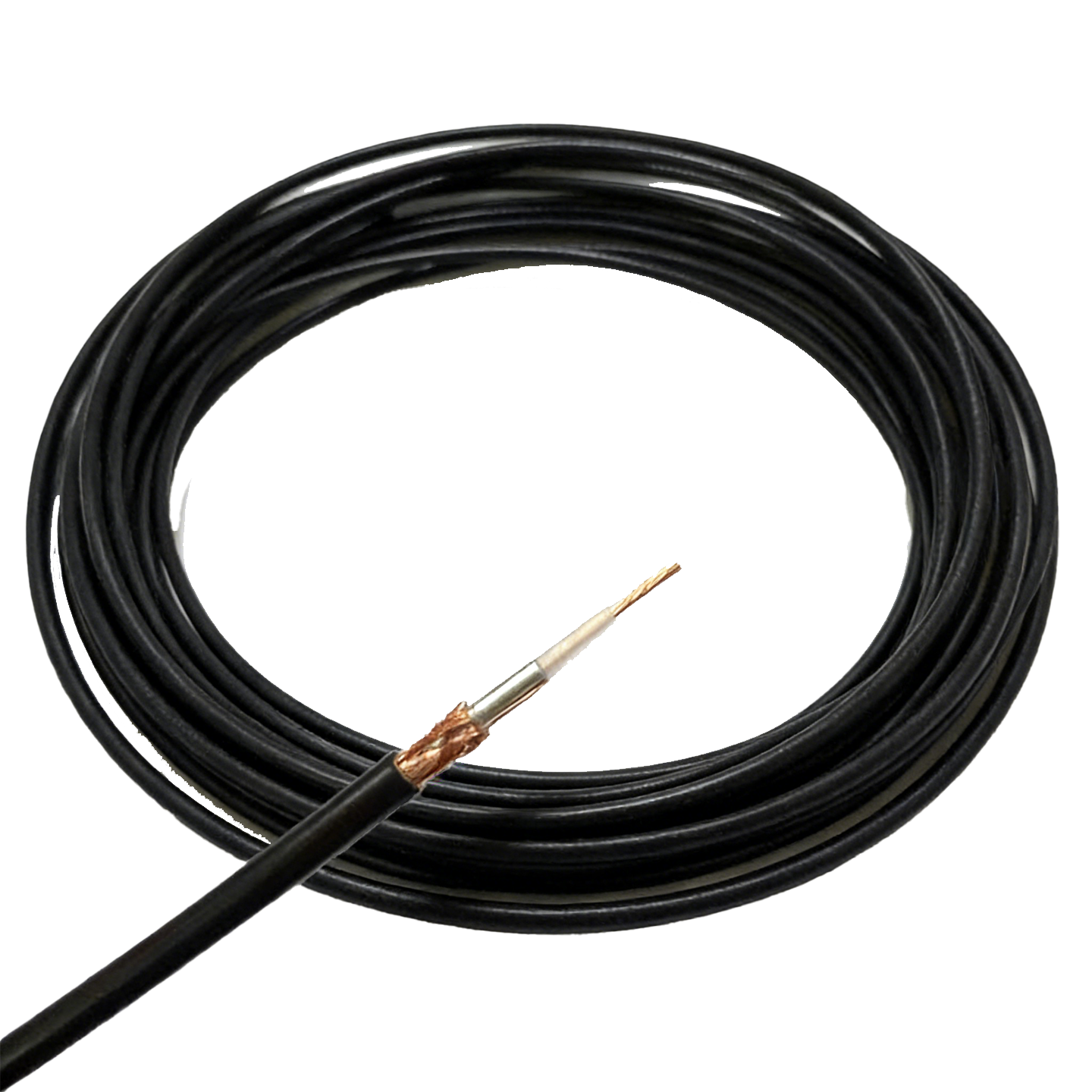
عوامل اصلی مؤثر بر عملکرد مجموعههای کابلهای هممحور
چگونه ساختار هممحور امکان امپدانس کنترلشده و مقاومت در برابر تداخل الکترومغناطیسی (EMI) را فراهم میکند
یک مجموعهی کابل هممحور از طریق هندسهی دقیق هممرکز خود امپدانس کنترلشده را به دست میآورد: هادی داخلی، عایق دیالکتریک، زره فلزی و روکش خارجی، تشکیلدهندهی یک خط انتقال قابل پیشبینی هستند. مادهی دیالکتریک — که معمولاً پلیاتیلن جامد یا متخلخل، PTFE یا FEP است — سرعت انتشار را تعیین کرده و امپدانس مشخصه (مانند ۵۰ اهم یا ۷۵ اهم) را در طول کل کابل ثابت نگه میدارد. این یکنواختی بازتابهای سیگنال را به حداقل رسانده و وفاداری شکل موج را حفظ میکند.
مقاومت در برابر تداخل الکترومغناطیسی (EMI) ناشی از توانایی پوشش محافظ در مهار کردن میدانهای الکترومغناطیسی است. پوششهای بافتدار از مس یا فویل آلومینیوم با پوشش ≥۹۰٪، تداخل رادیویی خارجی (RFI) را مسدود کرده و از انتشار سیگنال جلوگیری میکنند. در کاربردهای پ demanding مانند زیرساختهای ارتباطی ۵G و سیستمهای MRI، مجموعههای دارای دو یا سه لایه محافظ، ایزولاسیونی بیش از ۱۰۰- دسیبل را فراهم میکنند—که برای حفظ صحت سیگنال در محیطهای الکتریکی پرسر و صدا حیاتی است.
امپدانس ۵۰ اهم در مقابل ۷۵ اهم: الزامات تطبیق امپدانس و پیامدهای تلفات بازتاب
عدم تطبیق امپدانس منبع اصلی تلفات توان و اعوجاج در مجموعه کابلهای کوآکسی است. سیستم ۵۰ اهم انتقال توان را بهینهسازی میکند و بنابراین استاندارد برای ارسالکنندههای RF، تجهیزات آزمایشی و زیرساختهای بیسیم است. در مقابل، سیستمهای ۷۵ اهم به جای انتقال توان، اتلاف کمتر را در فواصل طولانی اولویت قرار میدهند—که برای سیستمهای تلویزیون کابلی (CATV)، ویدئوهای پخششده و اینترنت پهنباند ایدهآل است.
| پارامترها | 50 Ω | 75 Ω |
|---|---|---|
| کاربرد اصلی | ارسالکنندههای RF، تجهیزات آزمایشی، زیرساختهای بیسیم | تلویزیون کابلی (CATV)، ویدئوهای پخششده، اینترنت پهنباند |
| بازتاب سیگنال در نقطه عدم تطبیق امپدانس | تلفات تقریبی ۱۰٪ توان هنگام رانش بار ۷۵ اهم | تقریباً ۱۲٪ افت در هنگام رانندگی با بار ۵۰ اهم |
| اتلاف معمول در فرکانس ۱ گیگاهرتز (مقایسه RG-58 با RG-6) | ۲۴ دسیبل بر ۱۰۰ فوت | ۱۵ دسیبل بر ۱۰۰ فوت |
| جریمه نسبت موج ایستا ولتاژ (VSWR) | بالا (≥۲٫۰:۱) در صورت عدم تطبیق امپدانس | متوسط (≥۱٫۵:۱) |
حتی عدم تطبیقهای کوچک نیز به سرعت تشدید میشوند: استفاده از مجموعه کابل کواکسیال ۵۰ اهم در یک سیستم ۷۵ اهمی میتواند افتی بیش از ۰٫۵ دسیبل را در هر اتصالدهنده ایجاد کند و نسبت سیگنال به نویز را کاهش دهد. تطبیق امپدانس در تمام اجزای کابل، اتصالدهنده و پایانه، شرطی غیرقابل انکار برای انتقال سیگنال با کیفیت بالا است.
اتلاف، پهنای باند و سیلدینگ — معیارهای متقابلاً وابسته برای صحت سیگنال
تضعيف با افزایش فرکانس به دلیل اثر پوستی و تلفات دیالکتریک افزایش مییابد. اگرچه استفاده از رساناها با سطح مقطع بزرگتر و دیالکتریکهای با تلفات کمتر، تضعیف را کاهش میدهد، اما این عوامل همچنین بر امپدانس و انعطافپذیری کابل تأثیر میگذارند. پهنای باند—یعنی محدوده فرکانسی قابل استفاده پیش از آنکه تضعیف به سطحی غیرقابل تحمل برسد—وابسته به این تعادل است. به عنوان مثال، کابل استاندارد RG‑6 تا فرکانس ۳ گیگاهرتز پشتیبانی میکند، در حالی که کابلهای پremium با تلفات کم مانند LMR‑400 پهنای باند قابل استفاده را تا ۶ گیگاهرتز گسترش میدهند و تلفات آن در این فرکانس کمتر از ۲۰ دسیبل در هر ۱۰۰ فوت است.
کارایی سیستم محافظتدهنده بهطور مستقیم بر تضعیف و پهنای باند تأثیر میگذارد. محافظت ضعیف با اجازه دادن به تداخلات خارجی برای جفتشدن با مسیر سیگنال، سطح نویز را افزایش داده و در نتیجه پهنای باند قابل استفاده را کاهش میدهد. از سوی دیگر، خمشدن بیش از حد کابل، دیالکتریک را فشرده کرده و ظرفیت خازنی و بازتاب را افزایش میدهد. مهندسان باید تضعیف، پهنای باند و محافظت را بهعنوان متغیرهای وابسته به یکدیگر — نه مشخصاتی مستقل — در نظر بگیرند. یک قاعده طراحی عملی: برای جبران عواملی مانند پیرشدن، تغییرات دما و تغییرپذیری اتصالدهندهها، حداقل حاشیهای معادل ۶ دسیبل در بودجه تلفات در بالاترین فرکانس کاری در نظر گرفته شود.
مقایسه انواع کابلهای هممحور: سری RG، کابلهای کمتلفات، نیمهصلب و میکروهممحور
RG-58، RG-6 و RG-400: انعطافپذیری، مشخصات تلفات و کاربردهای رایج مجموعههای کابلی هممحور
کابلهای سری RG همچنان بهعنوان کابلهای اصلی مورد استفاده در مجموعههای کابلی هممحور تجاری و صنعتی باقی ماندهاند. کابل RG‑58 (۵۰ اهم) انعطافپذیری عالی و راحتی بالایی در اتصال دارد و بنابراین برای کاربردهای کوتاهبرد و کمتوان مانند سیمهای تست آزمایشگاهی و اتصالات رادیوهای دستی مناسب است؛ اما تضعیف آن بالای ۱ گیگاهرتز بهطور قابلتوجهی افزایش مییابد. کابل RG‑6 (۷۵ اهم) با هادی مرکزی بزرگتر و عایق ضخیمتر، تلفات بسیار کمتری را در فواصل طولانی ارائه میدهد و این ویژگی آن را به انتخاب پیشفرض برای نصبهای تلویزیون کابلی (CATV)، ماهوارهای و پهنباند در محیطهای مسکونی و تجاری تبدیل کرده است. کابل RG‑400 (۵۰ اهم) با استفاده از بافت دو لایهای از مس آبکاریشده با نقره و عایق PTFE، عملکرد را ارتقا میبخشد و تحمل دماهای بالاتر، چرخههای خمش بیشتر و مقاومت بالاتر در برابر لرزش را فراهم میکند؛ این ویژگیها دلایل اصلی تعیین این کابل در مجموعههای کابلی هممحور صنایع هوافضا، دفاعی و ارتباطات سیار هستند.
کابلهای کمتلفات (مانند LMR-400) و نیمهسفت (مانند UT-141): تلفات درجی در فرکانس ۳ گیگاهرتز و مصالحههای مکانیکی
وقتی فرکانس یا فاصله از قابلیتهای سری RG فراتر رود، جایگزینهای کمتلفات و نیمهسفت ضروری میشوند. کابل LMR-400 (۵۰ اهم) در فرکانس ۳ گیگاهرتز تنها دارای تلفات ورودی ۶٫۶ دسیبل بر هر ۱۰۰ فوت است — که تقریباً یکسوم مقدار مربوط به RG‑58 میباشد — و این امر آن را به انتخابی رایج برای خطوط تغذیه آنتن در ایستگاههای پایه سلولی و سیستمهای آنتن توزیعشده (DAS) تبدیل میکند. کابلهای نیمهسفت مانند UT-141 (قطر ۰٫۱۴۱ اینچ) از یک هادی بیرونی مسی کاملاً جامد و دیالکتریک PTFE ماشینکاریشده با دقت بالا استفاده میکنند تا در فرکانس ۳ گیگاهرتز به تلفاتی حدود ۵ دسیبل بر هر ۱۰۰ فوت برسند. با این حال، سفتی این کابلها نیازمند شکلدهی دقیق و یکباره است؛ خمکردن مجدد آنها منجر به ناپیوستگیهای امپدانس و کاهش یکپارچگی محافظتی میشود.
تعادل مورد نظر روشن است: کابلهای انعطافپذیر کمتلفات، عملکرد الکتریکی را بهینه میکنند در عین حفظ قابلیت تعمیر و نگهداری در محل؛ در مقابل، کابلهای نیمهسفت پایداری فاز، محافظت و تکرارپذیری بهتری ارائه میدهند، اما برای مسیریابی و اتصال آنها نیازمند دقتی در سطح کارخانه است.
انتخاب اتصالدهنده و تطبیق امپدانس برای مجموعههای قابل اطمینان کابل کواکسیال
انواع F-Type، BNC، N-Type و SMA: محدوده فرکانسی، دوام و سازگاری با محیط
انتخاب اتصالدهنده به اندازه انتخاب کابل در مجموعههای کابل کواکسیال حیاتی است. اتصالدهندههای نوع F از نظر هزینه مقرونبهصرفه بوده و بهطور گسترده در نصبهای تلویزیون و ماهواره استفاده میشوند، اما محدودیت فرکانسی آنها حدود ۱ گیگاهرتز است و در صورت عدم آببندی مناسب، مستعد نفوذ رطوبت هستند. اتصالدهندههای BNC تا فرکانس ۴ گیگاهرتز پشتیبانی میکنند و دارای رابط قفلشونده سریع (بایونت) هستند که برای میزهای آزمایش و محیطهای با ارتعاش متوسط ایدهآل است. اتصالدهندههای N-Type ساختاری مقاوم و ضدآب دارند و عملکرد قابلاطمینانی تا ۱۱ گیگاهرتز ارائه میدهند؛ بنابراین استاندارد صنعتی برای زیرساختهای بیسیم بیرونی و اتصالات RF با توان بالا محسوب میشوند. اتصالدهندههای SMA با اتصال دقیق ۳۶ رشته در اینچ و کنترل دقیق تلرانس، پایداری خود را فراتر از ۱۸ گیگاهرتز حفظ میکنند و در کاربردهای فشرده و پرفرکانس مانند آنتنهای موجمیلیمتری و ماژولهای RF ضروری هستند.
بهطور حیاتی، تمام اتصالدهندهها باید با امپدانس نامی سیستم مطابقت داشته باشند—۵۰ اهم برای RF/داده و ۷۵ اهم برای ویدئو/پخش—تا از بازتابها جلوگیری شود و VSWR حفظ گردد.
پیامدهای VSWR ناشی از عدم تطبیق امپدانس — نمونههای واقعی در مجموعههای کابلی هممحور فرکانس بالا
عدم تطبیق امپدانس در هر نقطهای — از جمله اتصالدهندهها، انتقالها یا پورتهای بدون انتهای بستهشده — باعث بازتاب سیگنال، افزایش VSWR و کاهش توان تحویلشده میشود. اگرچه VSWR برابر با ۱٫۰:۱ نشاندهنده تطبیق کامل است، اما مقادیر بالاتر از ۱٫۵:۱ شروع به تأثیرگذاری قابلاندازهگیری بر عملکرد سیستم میکنند. در یک ایستگاه پایه سلولی، جایگزینی اتصالدهنده BNC با امپدانس ۷۵ اهم در مجموعه کابل هممحور ۵۰ اهمی میتواند VSWR را به بیش از ۲٫۰:۱ افزایش دهد و منجر به کاهش محدوده پوشش و افزایش تداخل کانالهای مشترک شود. در سیستمهای رادار و جنگ الکترونیک، حتی عدم تطبیق جزئی در رابطهای SMA میتواند امواج ایستا ایجاد کند که منجر به گرمشدن بیش از حد و آسیبرساندن به تقویتکنندههای حساس GaN میشود.
پیوستگی امپدانس ثابت — از منبع تا بار، در تمام اتصالدهندهها و گذارها — پایهای برای قابلیت اطمینان مجموعههای کابلی هممحور در فرکانسهای بالا است.
معیارهای انتخاب اختصاصی بر اساس کاربرد برای مجموعههای کابلی هممحور
کاربردهای تلویزیون/آنتن، CATV/اینترنت، زیرساختهای بیسیم و نصبهای در محیطهای سختگیرانه: عوامل تمایزکنندهٔ کلیدی
انتخاب مجموعههای مناسب کابلی هممحور نیازمند تطبیق خواص فیزیکی و الکتریکی با عوامل استرسزا مخصوص به کاربرد است: فرکانس، فاصله، مواجهه با محیط و انطباق با مقررات.
| کاربرد | مقاومت | کابل معمولی | ویژگی کلیدی |
|---|---|---|---|
| تلویزیون/آنتن | 75 Ω | RG-6 | تضعیف پایین در فرکانسهای VHF/UHF |
| CATV/اینترنت | 75 Ω | RG-6 یا RG-11 | اثربخشی بالای سیستم محافظت در برابر نفوذ/خروج سیگنال |
| زیرساخت بیسیم | 50 Ω | LMR-400 یا کابل فوم نیم اینچی | سهمیهی پایین تداخل غیرفعال (PIM) و تلفات پایین در باندهای سلولی |
| محیطهای سخت | ۵۰ یا ۷۵ اهم | دو لایه محافظ، ضد ضربه | سوکتهای مقاوم در برابر آب و هوا، محدوده دمای گسترده (۴۰- تا ۸۵+ درجه سانتیگراد) |
این تفاوتها تضمین میکنند که صحت سیگنال بهصورت بهینه حفظ شود، بدون اینکه طراحی بیشازحد پیچیده و پرهزینه باشد. برای مثال، استفاده از مجموعه کابل کواکسیال نیمهصلب گرانقیمت در خط اتصال تلویزیون خانگی، هزینه و پیچیدگی نصب را افزایش میدهد بدون اینکه مزیت عملیاتی قابلتوجهی ایجاد کند؛ در مقابل، استفاده از کابل RG-58 در یک ایستگاه ماکروی ۵G منجر به تضعیف بودجه اتصال (link budget) و عملکرد PIM میشود. انطباق مشخصات فنی با شرایط واقعی عملیاتی، ویژگی اصلی طراحی مؤثر مجموعههای کابل کواکسیال است.
آمادهاید تا عملکرد سیستم خود را با مجموعههای سفارشی کابل کواکسیال بهینهسازی کنید؟
مجموعههای کابل هممحور، ستون فقرات حیاتی انتقال سیگنال در تمامی سیستمهای الکترونیکی هستند—مجموعههای نامناسب میتوانند منجر به تضعیف سیگنال، توقف غیرمنتظره و بازگرداندن مجدد گرانقیمت محصولات از میدان شوند که این امر به شهرت برند شما آسیب میزند و اعتماد مشتریان را تضعیف میکند. با همکاری با تولیدکنندهای که هم ظرافتهای فنی عملکرد RF و هم نیازهای خاص تولید OEM را درک میکند، شما میتوانید یکپارچگی سیگنال پایدار، کاهش هزینه کل مالکیت و زمان کوتاهتر برای عرضه محصولات خود در بازار را به دست آورید.
برای مجموعههای کابلی هممحور و اتصالدهندههای RF با کیفیت صنعتی که دقیقاً مطابق با نیازهای سازنده تجهیزات اصلی (OEM) شما طراحی شدهاند، با شرکت الکترونیک آوشن زهنجیانگ همکاری کنید — شریک قابل اعتماد شما در تولید RF با بیش از ۳۰ سال تجربه تخصصی در این صنعت. ما دارای گواهیهای ISO 9001 و RoHS هستیم، کارخانهای به مساحت بیش از ۵۰۰۰ متر مربع را اداره میکنیم که مجهز به بیش از ۶۰ دستگاه تراش CNC پیشرفته است و روزانه تا ۶۰۰۰۰ واحد محصول با نرخ پذیرش اولیه (first-pass yield) بیش از ۹۸٫۵٪ تحویل میدهیم. خدمات جامع «یکپارچه» ما شامل مشاوره طراحی، بهینهسازی انتخاب قطعات، ساخت نمونههای سفارشی و حملونقل جهانی میشود. امروز با ما تماس بگیرید تا مشاوره فنی رایگان و بدون تعهد یا نمونه سفارشی رایگان برای بهینهسازی پروژه بعدی شما در حوزه RF دریافت کنید.
سوالات متداول (FAQ)
امپدانس در مجموعههای کابلی هممحور چیست؟
امپدانس معیاری برای اندازهگیری مقاومت در مقابل جریان متناوب در یک خط انتقال است. کابلهای هممحور معمولاً امپدانس ۵۰ Ω یا ۷۵ Ω را پشتیبانی میکنند تا وفاداری سیگنال را تضمین کرده و از بازتابها جلوگیری کنند.
چرا محافظت (shielding) در کابلهای هممحور اهمیت دارد؟
محافظت در برابر تداخل الکترومغناطیسی خارجی (EMI) را فراهم میکند و از انتشار سیگنال جلوگیری مینماید، بهگونهای که عملکرد قابلاطمینانی در محیطهای پرسر و صدا تضمین میشود.
تضعیف چگونه بر یکپارچگی سیگنال تأثیر میگذارد؟
تضعیف، قدرت سیگنال را در طول فاصله یا با تغییر فرکانس کاهش میدهد. استفاده از کابلها و اتصالدهندههای کمتلافی، میزان تضعیف را به حداقل میرساند و عرض باند را حفظ میکند.
برخی از کاربردهای رایج مجموعههای کابل هممحور (کواکسیال) کداماند؟
کاربردها شامل سیستمهای تلویزیونی/آنتن، تلویزیون کابلی (CATV)/اینترنت پهنباند، زیرساختهای بیسیم و نصبها در محیطهای سختگیرانه که نیازمند مقاومسازی در برابر عوامل جوی هستند، میباشند.
عدم تطبیق امپدانس چگونه بر نسبت موج ایستا ولتاژ (VSWR) تأثیر میگذارد؟
عدم تطبیق امپدانس منجر به بازتاب سیگنال میشود که نسبت موج ایستا ولتاژ (VSWR) را افزایش داده و توان مؤثر انتقالی را کاهش میدهد.
فهرست مطالب
- عوامل اصلی مؤثر بر عملکرد مجموعههای کابلهای هممحور
- مقایسه انواع کابلهای هممحور: سری RG، کابلهای کمتلفات، نیمهصلب و میکروهممحور
- انتخاب اتصالدهنده و تطبیق امپدانس برای مجموعههای قابل اطمینان کابل کواکسیال
- معیارهای انتخاب اختصاصی بر اساس کاربرد برای مجموعههای کابلی هممحور
- آمادهاید تا عملکرد سیستم خود را با مجموعههای سفارشی کابل کواکسیال بهینهسازی کنید؟
- سوالات متداول (FAQ)