 EN
EN

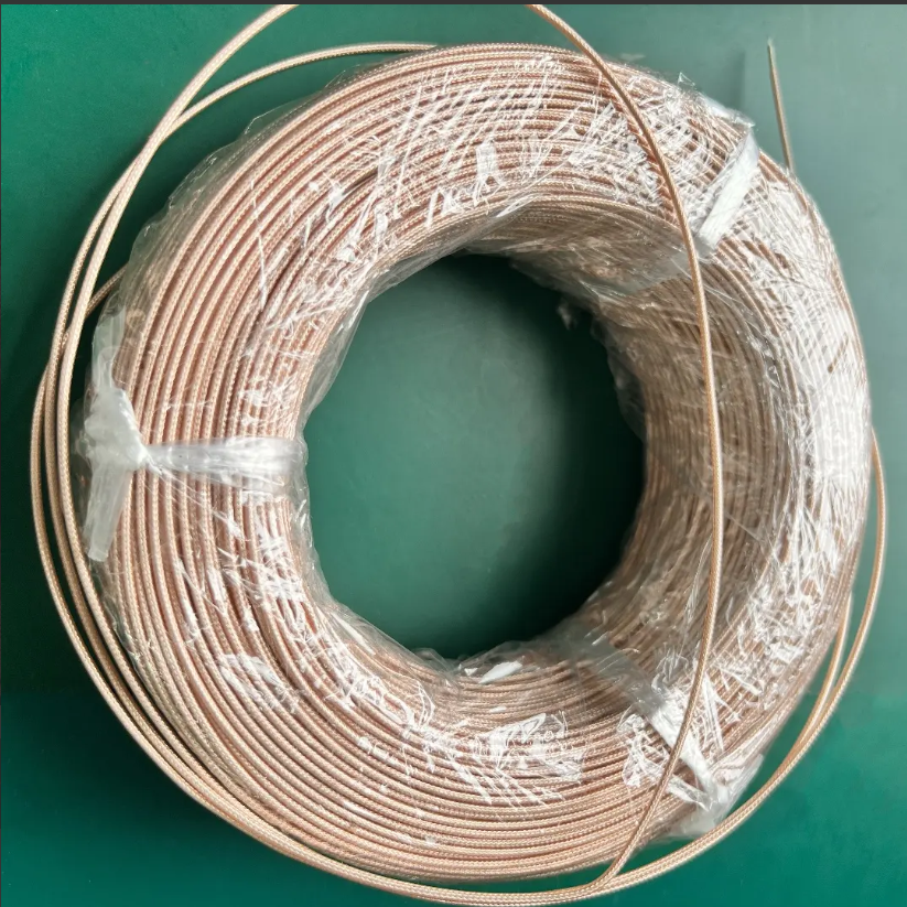
Explicación de los tipos de cables RG y sus especificaciones técnicas
Seleccionar el derecho Cable RG el tipo es fundamental para lograr una transmisión de señal fiable. Las especificaciones clave —impedancia, atenuación y eficacia del blindaje— afectan directamente el rendimiento y la durabilidad. Esta sección detalla los atributos técnicos de los cables RG más comunes para orientar su selección.
Comparación entre RG-6, RG-59 y RG-11: impedancia, atenuación y adecuación al caso de uso
Los tres principales tipos de cable RG mantienen una impedancia característica estándar de 75 Ω, optimizada para la compatibilidad con equipos de vídeo y banda ancha, así como para minimizar la reflexión de la señal. El cable RG-6 ofrece un rendimiento equilibrado para televisión por satélite residencial, internet de banda ancha y sistemas distribuidos de antenas (DAS), presentando una atenuación menor que la del RG-59 y mayor flexibilidad que la del RG-11. El RG-11, con su conductor central más grueso de 14 AWG, reduce la pérdida de señal en distancias largas, lo que lo convierte en la opción preferida para instalaciones troncales de CATV y aplicaciones comerciales que superan los 100 metros. El RG-59 sigue siendo viable únicamente para sistemas analógicos de CCTV o vídeo heredados de corta distancia; su mayor atenuación por encima de los 50 MHz limita su uso en aplicaciones modernas de alta frecuencia.
| Tipo de cable | Impedancia | Atenuación (por 100 pies a 1 GHz) | Tamaño del conductor central | Casos Principales de Uso |
|---|---|---|---|---|
| RG-59 | 75Ω | ~6,8 dB | 20 AWG | CCTV, vídeo analógico de corta distancia |
| RG-6 | 75Ω | ~5,6 dB | 18 awg | Televisión por satélite, banda ancha, DAS doméstica |
| RG-11 | 75Ω | ~3,7 dB | 14 AWG | CATV de larga distancia, instalaciones troncales |
Cómo afectan el apantallamiento, el dieléctrico y la calidad del conductor al rendimiento del cable RG
Tres elementos físicos fundamentales definen la resistencia de los cables RG en el mundo real:
- El blindaje : Las configuraciones de blindaje cuádruple —dos capas de lámina de aluminio y dos capas de cobre trenzado— ofrecen una atenuación de interferencias electromagnéticas (EMI) de hasta 85 dB, superando significativamente a las variantes de doble blindaje (~65 dB). Este nivel de protección es esencial cerca de líneas eléctricas, sistemas de calefacción, ventilación y aire acondicionado (HVAC) o maquinaria industrial.
- Dielectrico : El aislamiento de polietileno espumado reduce la capacitancia y las pérdidas de señal aproximadamente un 15 % en comparación con el polietileno sólido, preservando la fidelidad en amplios rangos de frecuencia.
- Conductor : El cobre libre de oxígeno (OFC) minimiza las pérdidas resistivas y resiste la corrosión en entornos húmedos —donde los núcleos de acero recubierto de cobre pueden degradarse hasta un 20 % en atenuación durante cinco años.
Instalación adecuada de cables RG: desde la planificación hasta la validación
Buenas prácticas de tendido: evitación de interferencias electromagnéticas (EMI), límites del radio de curvatura y esfuerzos mecánicos
Enrutamiento de los cables RG a una distancia mínima de 30 cm de las instalaciones eléctricas y de las luminarias fluorescentes para reducir la interferencia electromagnética. Respete los radios mínimos de curvatura —normalmente 10 veces el diámetro del cable para RG-6— para evitar torsiones, deformación de la pantalla o compresión dieléctrica que degraden de forma permanente la integridad de la señal. Sujete los cables cada 1,2–1,5 m mediante ganchos en J o bandejas portacables para eliminar el colgamiento y los puntos de tensión. En entornos industriales, las canalizaciones metálicas rígidas o flexibles ofrecen tanto protección física como aislamiento frente a interferencias electromagnéticas procedentes de motores y transformadores. Un estudio sobre conectividad de 2023 reveló que el cumplimiento de estos principios de enrutamiento redujo las pérdidas de señal medidas un 27 % en comparación con despliegues no estructurados.
Técnicas seguras de pelado y terminación para preservar la integridad de la pantalla
Utilice herramientas de despojado calibradas para exponer exactamente ¼ de pulgada del conductor central sin cortar ni deformar la trenza; una protección comprometida genera rutas de fuga de RF. Para los conectores de compresión, asegúrese de que el dieléctrico de espuma quede al ras del cuerpo del conector para mantener una transición de impedancia constante. Gire los cables de tierra en sentido horario antes de fijarlos a los bloques de terminación para maximizar el área de superficie de contacto y la conductividad. En entornos fríos (< 0 °C), caliente gradualmente los cables antes de manipularlos para evitar grietas en el dieléctrico. Estos pasos preservan la cobertura completa de blindaje de 360°, crítica para la inmunidad al ruido de RF en aplicaciones sensibles de radiodifusión o seguridad.
Pruebas de recorridos de cable RG: verificación de continuidad, pérdida de señal, puesta a tierra y protección contra sobretensiones
Valide cada recorrido instalado mediante este protocolo de cuatro pasos:
- Verificaciones de continuidad confirme trayectos de conductor ininterrumpidos utilizando un multímetro digital
- Mediciones de pérdida de señal compare la atenuación real (en dB por 100 pies) con las especificaciones del fabricante utilizando un medidor de RF calibrado
- Verificación de la puesta a tierra confirma una resistencia inferior a 1 ohmio entre todas las masas de los conectores y la tierra
- Pruebas de protección contra sobretensiones aplicar formas de onda transitorias estandarizadas para verificar el tiempo de respuesta de limitación y la supresión de tensión
Documentar todos los resultados conforme a los requisitos de la norma TIA-568-C.2. Cualquier tramo que exceda una pérdida de 3 dB por cada 100 pies a las frecuencias de operación debe volver a terminarse o sustituirse. Las auditorías de cableado estructurado indican que las pruebas periódicas anuales evitan el 74 % de los incidentes de degradación progresiva de la señal.
Selección e instalación de conectores para cables RG con vistas a una fiabilidad a largo plazo
Conectores de compresión, de crimpado y de rosca: requisitos de herramientas y durabilidad ambiental
La elección del conector afecta directamente la fiabilidad a largo plazo en distintas condiciones de instalación. Los conectores de engarce (crimp-on) ofrecen una alta resistencia mecánica cuando se aplican con herramientas de engarce de precisión, lo que los hace ideales para entornos con alta vibración, como las infraestructuras de transporte o los suelos de fábricas. Los conectores de compresión requieren una herramienta específica de compresión, pero proporcionan un sellado ambiental superior, resistiendo la entrada de humedad y la corrosión en despliegues al aire libre, subterráneos o costeros. Los conectores de rosca (screw-on) permiten un montaje rápido en campo sin necesidad de herramientas especializadas; sin embargo, su interfaz roscada es propensa a aflojarse bajo ciclos térmicos o vibración, lo que limita su uso a aplicaciones estables, interiores y de bajo riesgo, donde el acceso para mantenimiento es rutinario. Para instalaciones críticas para la misión o en entornos agresivos, priorice los conectores de compresión; para resistencia industrial a la vibración, elija los de engarce; reserve los de rosca para enlaces temporales o interiores de fácil acceso para mantenimiento.
Directrices de despliegue de cables RG específicas por aplicación
Elija el cable RG según la distancia, la frecuencia y las exigencias ambientales, no solo en función del costo o la disponibilidad. Para instalaciones de banda ancha o video digital superiores a 100 metros, la menor atenuación del RG-11 garantiza el cumplimiento de los umbrales de señal DOCSIS o ATSC. Para la distribución estándar de video, datos y sistemas de antenas distribuidas (DAS) en entornos residenciales, el RG-6 ofrece el equilibrio óptimo entre rendimiento, flexibilidad y costo. El RG-59 sigue siendo adecuado únicamente para enlaces analógicos de CCTV de corta distancia, inferiores a 50 metros. Verifique siempre la coincidencia de impedancia de 75 Ω y seleccione el nivel de apantallamiento acorde con la exposición local a interferencias electromagnéticas (EMI): apantallamiento cuádruple para zonas urbanas o industriales y apantallamiento doble para uso residencial típico.
Preguntas frecuentes
¿Qué significa «RG» en los cables RG?
«RG» significa «Radio Guide» (Guía de Radio), término que se originó en las especificaciones militares para cables coaxiales. Actualmente ya no denota parámetros técnicos específicos, pero sigue utilizándose ampliamente como identificador de tipos de cable.
¿Cuál es la diferencia entre los cables RG-59, RG-6 y RG-11?
El cable RG-59 es adecuado para enlaces analógicos de CCTV de corta distancia, el RG-6 equilibra costo y rendimiento para uso residencial, y el RG-11 presenta baja atenuación para aplicaciones de larga distancia.
¿Cuándo debo usar cables RG con blindaje cuádruple?
Se recomiendan los cables con blindaje cuádruple en entornos con alta interferencia electromagnética (EMI), como cerca de maquinaria industrial, líneas eléctricas o en zonas urbanas.
¿Qué herramienta es la más adecuada para pelar cables RG?
Una herramienta de pelado calibrada es la ideal, ya que expone con precisión el conductor central sin dañar el blindaje ni el dieléctrico.
¿Con qué frecuencia se deben probar las instalaciones de cables RG?
Se recomienda realizar pruebas anuales para prevenir la degradación de la señal y garantizar la fiabilidad del sistema.
Tabla de contenidos
- Explicación de los tipos de cables RG y sus especificaciones técnicas
-
Instalación adecuada de cables RG: desde la planificación hasta la validación
- Buenas prácticas de tendido: evitación de interferencias electromagnéticas (EMI), límites del radio de curvatura y esfuerzos mecánicos
- Técnicas seguras de pelado y terminación para preservar la integridad de la pantalla
- Pruebas de recorridos de cable RG: verificación de continuidad, pérdida de señal, puesta a tierra y protección contra sobretensiones
- Selección e instalación de conectores para cables RG con vistas a una fiabilidad a largo plazo
- Directrices de despliegue de cables RG específicas por aplicación
- Preguntas frecuentes