 EN
EN

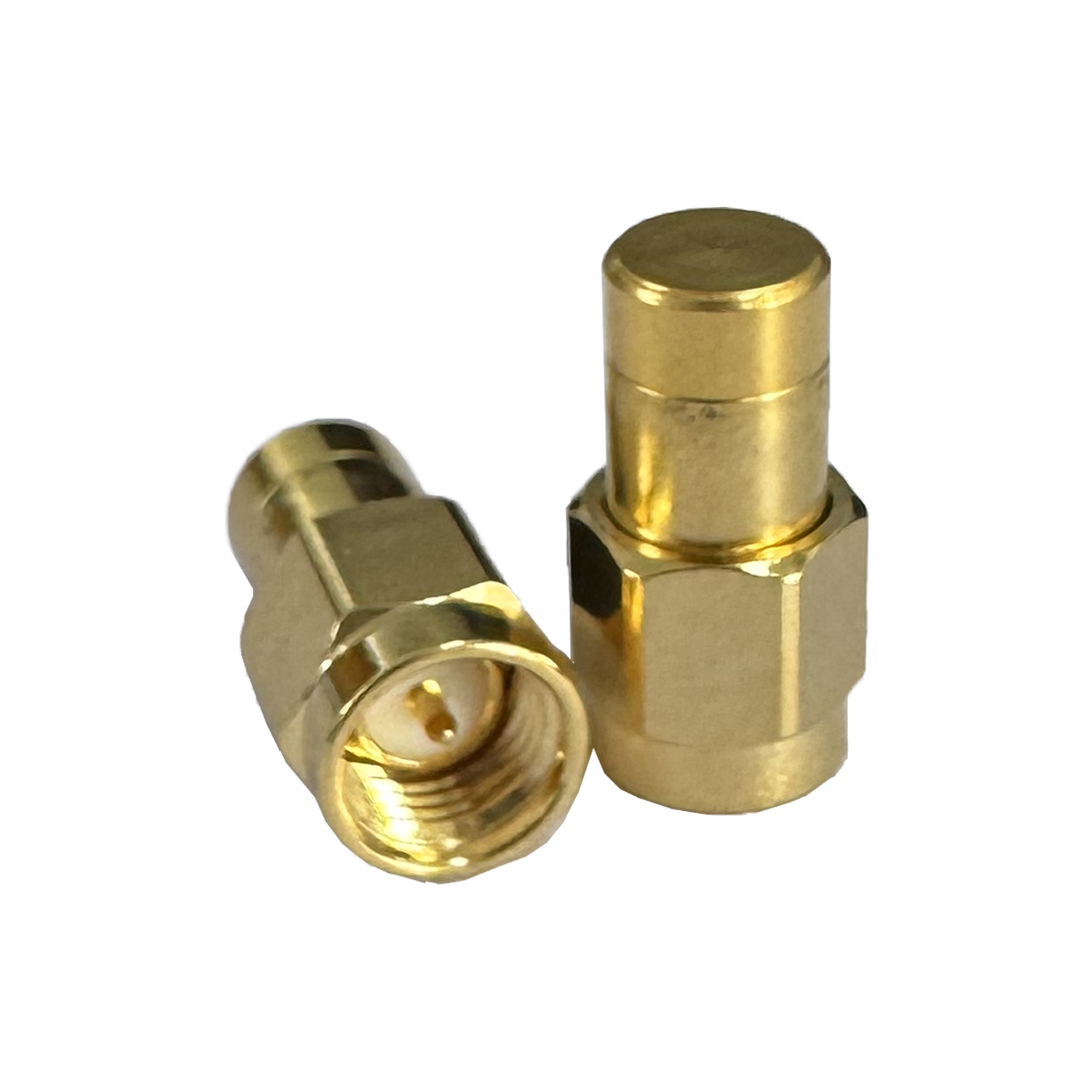
Understanding RF Coaxial Connector Efficiency Metrics
How Insertion Loss, VSWR, and Return Loss Quantify RF Efficiency
RF coaxial connector efficiency is quantified through three interrelated parameters: insertion loss, Voltage Standing Wave Ratio (VSWR), and return loss. Insertion loss measures signal attenuation in decibels (dB) as energy passes through the connector—directly affecting power delivery and system sensitivity. For instance, a 0.1 dB loss at 6 GHz reduces effective receiver gain by approximately 2.3%. VSWR reflects impedance matching quality by comparing incident to reflected wave amplitudes; values ≤1.5:1 indicate minimal reflection and are widely accepted as optimal for high-fidelity transmission. Return loss complements VSWR by expressing reflected power logarithmically—higher values signify better impedance continuity, with >20 dB generally recommended for stable broadband operation. Together, these metrics define how well a connector preserves signal integrity across its operating band.
| Parameter | Cause | Impact on System | Ideal Value |
|---|---|---|---|
| Insertion Loss | Conductor resistance, dielectric absorption | Reduced signal power | <0.1 dB @ 6 GHz |
| VSWR | Impedance mismatches | Signal reflections, power loss | ≤1.5:1 |
| Return Loss | Discontinuities in impedance | Reflected energy, phase distortion | >20 dB |
Frequency Range, Power Handling, and Environmental Factors in Real-World RF Coaxial Connector Performance
Frequency fundamentally governs RF coaxial connector behavior. Insertion loss rises with frequency due to skin effect and dielectric dispersion—connectors performing well at 3 GHz may exhibit 150% higher loss at 40 GHz. Power handling depends on conductor cross-section and dielectric thermal stability; exceeding rated limits (e.g., >500W average at 2.4 GHz) risks irreversible dielectric breakdown or arcing.
Environmental stressors further modulate performance:
- Temperature: Thermal cycling between –55°C and +125°C can induce contact relaxation, increasing VSWR by up to 15%.
- Vibration: Mechanical shock degrades mating surface integrity, elevating insertion loss by 0.05–0.2 dB—particularly critical in mobile or aerospace platforms.
- Humidity: Moisture ingress alters local dielectric constant, introducing impedance discontinuities that degrade return loss and promote corrosion.
These variables underscore why lab-rated specs alone are insufficient: real-world reliability demands validation under application-specific environmental loads.
Comparing Common RF Coaxial Connector Models by Application Bandwidth
Choosing the right RF coaxial connector requires balancing electrical performance, mechanical durability, and environmental suitability—not just bandwidth. Below 6 GHz, several mature designs offer distinct advantages tailored to deployment context.
SMA vs. N-Type: Trade-offs in RF Efficiency Below 6 GHz
The SMA connector excels in compact, high-density applications such as PCB-mounted RF modules and test instrumentation. Its precision-machined interface delivers low insertion loss and stable VSWR up to 18 GHz, though its smaller center pin and thinner dielectric limit average power handling to ~250W at 2.4 GHz. In contrast, the N-Type connector—rated to 11 GHz—features a larger conductive path and ruggedized, weatherproof construction ideal for outdoor base stations and high-power transmitters. While marginally higher in insertion loss than SMA under benign conditions, its mechanical resilience ensures consistent VSWR and return loss across temperature extremes and vibration profiles. Thus, SMA prioritizes space and electrical fidelity; N-Type prioritizes long-term reliability in harsh environments.
TNC and BNC: Balancing Mechanical Robustness and RF Coaxial Connector Efficiency in Dynamic Environments
TNC and BNC connectors address mechanical instability in dynamic systems—but with divergent trade-offs. The TNC’s threaded coupling maintains secure, repeatable mating under sustained vibration or thermal cycling, preserving impedance continuity and delivering reliable VSWR up to 12 GHz. This makes it preferred for radar arrays, avionics subsystems, and field-deployed communications gear. The BNC, limited to 4 GHz and secured via bayonet lock, enables rapid connection/disconnection but sacrifices RF consistency: its looser mechanical tolerance increases susceptibility to intermittent contact and higher insertion loss in high-shock scenarios. While suitable for benchtop test equipment where speed outweighs millimeter-wave stability, BNC should be avoided in mission-critical moving platforms where even minor impedance fluctuations risk system-level degradation.
High-Frequency RF Coaxial Connector Models: Precision Beyond 40 GHz
2.92 mm and 2.4 mm Connectors — Design, Performance Limits, and Interchangeability Risks
Above 40 GHz, standard connectors like SMA reach fundamental physical limits. Precision millimeter-wave interfaces—including the 2.92 mm and 2.4 mm—are engineered to minimize mode conversion, maintain tight impedance control, and ensure sub-micron repeatability. The 2.92 mm connector supports frequencies up to 40 GHz with excellent insertion loss and VSWR repeatability, commonly used in satellite ground stations and microwave backhaul. The 2.4 mm extends usable bandwidth to 50 GHz and features enhanced mechanical rigidity and tighter manufacturing tolerances—making it the preferred choice for military-grade test systems and high-accuracy calibration labs.
A key engineering risk lies in mechanical interchangeability: while the 2.92 mm shares outer dimensions with SMA and 3.5 mm connectors, its internal dielectric support geometry differs significantly. Forced mating can damage delicate insulator shoulders and distort center conductors—degrading VSWR and risking permanent interface damage. The 2.4 mm connector is not mechanically compatible with SMA, 3.5 mm, or 2.92 mm types; it only safely mates with 1.85 mm interfaces. Misalignment—even microns—introduces measurable impedance discontinuities at these frequencies. Engineers must verify both electrical specifications and mechanical compatibility before integration to avoid costly rework or measurement uncertainty.
Material Science and Interface Engineering Behind RF Coaxial Connector Efficiency
RF coaxial connector efficiency emerges from synergistic material science and nanoscale interface engineering. Low-loss dielectrics—such as expanded PTFE or air-spaced ceramic composites—minimize absorption and dispersion across wide bandwidths. Conductors rely on high-purity copper alloys with controlled gold plating (typically 0.76–2.54 µm thick) to balance conductivity, hardness, and corrosion resistance—critical for maintaining low surface resistance over thousands of mating cycles.
Mechanical integrity is equally vital: advanced nickel underplating prevents copper diffusion into gold, while specialized passivation techniques enhance moisture resistance. Contact geometry—including center pin concentricity, shoulder radius, and dielectric protrusion—is held to sub-5 µm tolerances to ensure consistent 50 Ω impedance transition across the mated interface. These precise material and geometric controls collectively suppress parasitic modes, reduce reflection-induced phase distortion, and sustain signal fidelity from DC through millimeter-wave bands—transforming theoretical design into field-proven reliability.
Ready to Select the Optimal RF Coaxial Connectors for Your OEM Systems?
RF coaxial connectors are the unsung backbone of all electronic systems—substandard connectors can cause signal degradation, unexpected downtime, and costly field recalls that damage your brand reputation and erode customer trust. By partnering with a manufacturer that understands both the technical nuances of RF performance and the unique requirements of OEM production, you’ll unlock consistent signal integrity, reduced total cost of ownership, and faster time-to-market for your products.
For industrial-grade RF coaxial connectors and custom cable assemblies tailored to your exact application requirements, partner with Zhenjiang Aoxun Electronic—your trusted OEM manufacturing partner with 30+ years of specialized RF industry experience. We hold ISO 9001 and RoHS certifications, operate a 5,000+ square meter factory equipped with 60+ CNC lathes, and deliver up to 60,000 units daily with first-pass yields exceeding 98.5%. Our comprehensive one-stop services include design consultation, connector selection optimization, custom prototyping, and global shipping. Contact us today for a no-obligation engineering consultation or free custom sample to optimize your next RF project.
FAQ Section
What is insertion loss in RF coaxial connectors?
Insertion loss quantifies the reduction in signal strength as it travels through a connector, expressed in decibels (dB). Lower insertion loss indicates better performance and minimal signal attenuation.
What is VSWR and why is it important?
Voltage Standing Wave Ratio (VSWR) measures impedance matching quality between components. A VSWR value ≤1.5:1 is considered optimal, minimizing signal reflections for efficient transmission.
How does return loss affect RF efficiency?
Return loss measures reflected power in a logarithmic scale. Higher return loss values (>20 dB) indicate better impedance continuity and reduced signal distortion.
How do environmental factors impact RF coaxial connector performance?
Factors like temperature, vibration, and humidity affect connector behavior. For instance, extreme temperatures can increase VSWR, while moisture ingress can degrade return loss and cause corrosion.
What are the key differences between SMA and N-Type connectors?
SMA connectors are compact and excel in high-density applications, while N-Type connectors are ruggedized for outdoor and high-power use. SMA focuses on electrical fidelity, while N-Type emphasizes reliability under harsh conditions.
Table of Contents
-
Understanding RF Coaxial Connector Efficiency Metrics
- How Insertion Loss, VSWR, and Return Loss Quantify RF Efficiency
- Frequency Range, Power Handling, and Environmental Factors in Real-World RF Coaxial Connector Performance
- Comparing Common RF Coaxial Connector Models by Application Bandwidth
- SMA vs. N-Type: Trade-offs in RF Efficiency Below 6 GHz
- TNC and BNC: Balancing Mechanical Robustness and RF Coaxial Connector Efficiency in Dynamic Environments
- High-Frequency RF Coaxial Connector Models: Precision Beyond 40 GHz
- Material Science and Interface Engineering Behind RF Coaxial Connector Efficiency
- Ready to Select the Optimal RF Coaxial Connectors for Your OEM Systems?
- FAQ Section