 EN
EN

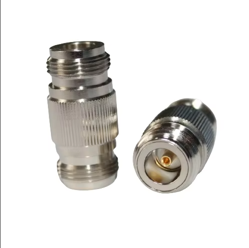
معايير أساسية لاختيار موصلات RF المحورية لتحقيق أقصى كفاءة
المقابس المستقيمة مقابل المقابس ذات الزاوية اليمنى، والجنس (ذكري/أنثوي)، والاستقطاب، وتصميم دبوس المركز وتأثيرها على فقد الإدخال وإعادة التكرار
اختيار الأنسب موصل كهربي مركزي (RF Coaxial Connector) يؤثر التصميم مباشرةً على كفاءة النظام من خلال فقد الإدخال والتكرارية الميكانيكية. وتوفّر الموصلات المستقيمة سلامة ممتازة لمسار الإشارة في التركيبات الثابتة، بينما توفر الموصلات ذات الزاوية القائمة فوائد في توفير المساحة ضمن التجميعات المدمجة—مع ملاحظة أن عدم استمرارية المعاوقة المتأصلة فيها تزيد من فقد الإدخال بمتوسط ٠,٣ ديسيبل مقارنةً بالموصلات المستقيمة (مجلة المايكروويف، ٢٠٢٣). ويمنع توحيد النوع (ذكر/أنثى) والاستقطاب حدوث أخطاء في التوصيل تؤدي إلى انعكاس الإشارة؛ كما تقلل الخيارات ذات الاستقطاب العكسي من مخاطر الانفصال العرضي في البيئات الخاضعة للاهتزاز. ويبقى تصميم دبوس المركز حاسماً بنفس القدر: إذ تحافظ الدبابيس المصنوعة من النحاس البريليوم المطلية بالذهب على متانة التلامس بعد أكثر من ٥٠٠ دورة توصيل، في حين تظهر البدائل النحاسية تآكلاً في الطلاء بعد ٢٠٠ دورة فقط—مما يرفع المقاومة بنسبة ١٥٪. ولتحقيق تكرارية حاسمة للمهمة، يُوصى بإعطاء الأولوية للموصلات التي تم التحقق من مطابقتها للمواصفة العسكرية MIL-STD-348، والتي تشترط ألا يتجاوز انحراف فقد الإدخال ٠,١ ديسيبل عبر ١٠٠٠٠ دورة توصيل.
نطاق التردد، وقدرة التحمّل، والتصنيفات البيئية في عمليات النشر الصناعي الفعلية
تتطلب الكفاءة التشغيلية مواءمة دقيقة بين مواصفات موصلات التردد اللاسلكي المتماسكة (RF coaxial) ومتغيرات النشر. وتؤدي عدم مطابقة نطاق التردد إلى توهين شديد: فموصلات الـ SMA تدعم حتى 18 غيغاهيرتز في البيئات المخبرية، لكن أداؤها يتدهور عند تجاوز 6 غيغاهيرتز في البيئات الصناعية بسبب تسخين العازل وانحراف التحملات الميكانيكية. أما قدرة التحمُّل على الطاقة فتتطلّب خفض التصنيف — مثلاً، الموصل المُصنَّف لتحمل 500 واط عند 3 غيغاهيرتز يدعم عادةً فقط 300 واط عند 10 غيغاهيرتز نظراً لخسائر تأثير الجلد (وفقاً للمعيار IEC 61169-1، الملحق باء). والمتانة البيئية شرطٌ لا غنى عنه لتحقيق الموثوقية الصناعية. وللتعرُّض للمواد الكيميائية المسببة للتآكل، يلزم استخدام أجسام من النيكل مطلية بالذهب مع إغلاق وفق درجة الحماية IP68 للحفاظ على معامل انعكاس الجهد (VSWR) أقل من 1.25 حتى في ظروف الرطوبة بنسبة 85%. أما في حالات التغير الحراري القصوى (من –55°م إلى +185°م)، فإن الموصلات المصنوعة من الفولاذ المقاوم للصدأ مع واجهات عازلة هوائية تمنع انجراف الإشارة الناتج عن التمدد الحراري. ولا يزال التقييم وفق المعيار MIL-STD-810H المعيار المرجعي الحاسم للتطبيقات المتعلقة بالنقل والدفاع، حيث يؤدي الفشل فيها إلى تعطيل الاستمرارية التشغيلية.
مواصفات موصلات الترددات الراديوية المركبة التي تؤثر مباشرةً على كفاءة النظام
مطابقة المعاوقة، ونسبة الموجة الراكدة الجهدية (VSWR) (<1.25)، وفقدان الانعكاس (>20 ديسيبل) كمعايير للكفاءة
تُعد مطابقة المعاوقة بدقة شرطًا لا غنى عنه لتقليل انعكاس الإشارة في أنظمة الترددات الراديوية. وتضمن نسبة الموجة الراكدة الجهدية (VSWR) الأقل من 1.25 كفاءة نقل طاقة تفوق 98%، بينما يدل فقدان الانعكاس الذي يتجاوز 20 ديسيبل على الحد الأدنى من الطاقة المنعكسة. وتؤثر هذه المقاييس تأثيرًا مباشرًا على سعة الشبكة؛ إذ يمكن أن يؤدي ارتفاع قيمة VSWR بمقدار 0.1 فقط إلى ظهور تأخّرٍ قابل للقياس في نظم النقل الخلفي لشبكات الجيل الخامس (5G). ويستلزم الحفاظ على هذه المعايير استخدام موصلات مُصمَّمة وفقًا لتسامحات ميكانيكية دقيقة جدًّا، لأن أي انحرافات تتراكم عبر سلاسل الترددات الراديوية متعددة المراحل وتُضعف الكفاءة من الطرف إلى الطرف.
مواد الطلاء (الذهب، والفضة، والنيكل) والأداء الحراري/المقاوم للتآكل عند الترددات فوق 3 غيغاهيرتز
عند الترددات التي تتجاوز ٣ غيغاهيرتز، يُحدِّد اختيار مادة الطلاء الموثوقية على المدى الطويل. ويوفِّر الذهب مقاومةً فائقةً للتآكل، لكنه يواجه قيودًا حراريةً تفوق ١٢٥°م. أما الفضة فهي توفر أفضل توصيل كهربائي، لكنها تتطلب إغلاقًا محكمًا لمنع تلونها بالكبريتيد في البيئات الصناعية. ويجسِّد النيكل توازنًا بين المتانة الميكانيكية القوية والكفاءة من حيث التكلفة والاستقرار عند درجات الحرارة المرتفعة. وفيما يلي مقارنةٌ بين أداء طبقات الطلاء في ظروف التشغيل القاسية:
| المادة | التوصيل الكهربائي (MS/م) | الحد الأقصى لدرجة الحرارة (°م) | المقاومة للتآكل | كفاءة التكلفة |
|---|---|---|---|---|
| ذهب | 44.5 | 125 | ممتاز | منخفضة |
| فضي | 63.0 | 200 | متوسطة* | متوسطة |
| النيكل | 14.3 | 500 | جيد | عالية |
*يتطلب إغلاقًا بيئيًّا إضافيًّا
تكشف اختبارات التغير الحراري الدوري أن موصلات التوصيل المتماسكة عالية التردد (RF) المطلية بالنيكل تتحمّل عددًا من الصدمات الحرارية يساوي ثلاثة أضعاف ما تتحمله النسخ المطلية بالفضة في تطبيقات الاتصالات السلكية واللاسلكية الخارجية. وتتمثل الاستراتيجية المثلى لطلاء هذه الموصلات في الجمع بين خصائص المادة وتقنيات التقوية البيئية — مثل التمرير أو الطلاءات المركبة — للحفاظ على فقد الإدخال (Insertion Loss) دون ٠٫١ ديسيبل على مدى عمر افتراضي يبلغ عقدًا من الزمن.
حماية سلامة الإشارة عبر أنواع الموصلات المتماسكة عالية التردد (RF) الشائعة
إدارة الانقطاعات وتأثير الجلد في موصلات SMA وN-Type وBNC وU.FL/IPEX
تعتمد سلامة الإشارة على تقليل الانقطاعات والتحكم في تأثير الجلد عبر أنواع الموصلات الترددية الراديوية المحورية الشائعة. وتواجه موصلات SMA عدم تطابق في المعاوقة عند الترددات الأعلى من ١٨ جيجاهرتز بسبب التسامحات الميكانيكية (±٠٫٠٠٥ بوصة)، بينما توفر موصلات N-Type سعة تشتت أقل ومقاومة أفضل للاهتزاز. أما اتصال موصلات BNC الدوراني (البيونيه) فيُحدث مقاومة تلامس متقطعة تحت دورة التغير الحراري، ما يزيد من فقدان الإدخال بمقدار ٠٫٢ ديسيبل لكل ١٠٠ دورة. وتتعامل موصلات U.FL/IPEX المصغَّرة مع تأثير الجلد — حيث يمر ٩٠٪ من التيار ضمن عمق ٢ ميكرومتر من السطح عند تردد ١٠ جيجاهرتز — باستخدام تلامسات من النحاس البريليوم مطلية بالذهب، مما يقلل التوهين بنسبة ١٥٪ مقارنةً بالطلاء النيكل. ومن الاستراتيجيات الفعالة للتخفيف من هذه الآثار:
- استخدام أدوات شد مخصصة لكل نوع من الموصلات (مثل: عزم شد يتراوح بين ٧–١٠ إنش-رطل لموصلات SMA) لضمان توزيع متساوٍ لضغط التلامس
- استخدام حشوات عازلة في المحولات الزاوية القائمة للحد من أوضاع الموجة التوجيهية
- اختيار الإصدارات المطلية بالفضة للتطبيقات التي تزيد تردداتها عن ٦ جيجاهرتز لتقليل مقاومة السطح
أفضل الممارسات المتبعة في دمج كابلات الترددات الراديوية مع الموصلات لتقليل الفقد
يؤمِنُ التوافق الصحيح بين الكابل والموصل (الاتصال) خرائط تطابقٍ متسقةً لمقاومة الدخل وفقدان الإشارة الأدنى. ويجب مطابقة نوع الكابل مع نطاق التردد الخاص بالموصل، ومعدل القدرة المسموح به، والملاءمة الميكانيكية. ولضمان الموثوقية، تهيمن ثلاث طرق لتوصيل الكابلات (إنهاء التوصيل): الضغط (Crimp)، والتثبيت بالمشبك (Clamp)، واللحام (Solder). ويوفِّر الضغط تجميعًا سريعًا وقابلًا للتكرار مع فقدان إدخالي منخفض عند تنفيذه باستخدام أدوات معايرة بدقة. أما موصلات التثبيت بالمشبك فتوفر قبضة ميكانيكية آمنة دون الحاجة إلى اللحام — وهي مثالية لإصلاحات الموقع الميداني. أما اللحام فيحقِّق أقل مقاومة كهربائية، لكنه يتطلَّب عمالة ماهرة وينطوي على خطر التلف الحراري. ويتحقق معيار الآي إي سي 61169-12 من الأداء الميكانيكي والكهربائي لهذه الطرق الثلاث، ويحدِّد عزم الدوران، وقوة السحب، وحدود معامل الانعكاس الموجي القياسي (VSWR). ويؤدي اختيار طريقة إنهاء التوصيل المناسبة استنادًا إلى بيئة التركيب والخبرة المتاحة مباشرةً إلى الحد من فقدان الانعكاس وتمديد عمر الموصل. ويمكن أن يؤدي التوصيل غير المتوافق إلى تدهور أداء نظام موصلات RF محورية عالية الجودة بنسبة تفوق 1 ديسيبل. ويجب دائمًا التحقق من الطريقة المختارة مقابل مواصفات الشركة المصنِّعة وخصائص العزل الكهربائي للكابل للحفاظ على سلامة الإشارة عند الترددات فوق 3 غيغاهيرتز.
قسم الأسئلة الشائعة
ما الفرق الرئيسي بين موصلات التردد اللاسلكي المستقيمة والموصلة ذات الزاوية القائمة؟
توفر موصلات التردد اللاسلكي المستقيمة سلامةً فائقةً في مسار الإشارة، بينما تم تصميم الموصلات ذات الزاوية القائمة للاستفادة القصوى من المساحة المتاحة في التجميعات، لكنها قد تؤدي إلى زيادة فقد الإدخال.
لماذا يُستخدم التغليف الذهبي للدبابيس المركزية؟
يؤمن التغليف الذهبي متانة التوصيل ويوفر أقل قدرٍ ممكن من التآكل، لا سيما في التطبيقات عالية التردد التي تتطلب دورات توصيل وتوصيل متكررة.
ما التصنيفات البيئية لمُوصِلات التردد اللاسلكي المحورية؟
تساعد التصنيفات البيئية مثل IP68 في ضمان قدرة الموصلات على مقاومة الرطوبة والتآكل ودورات درجات الحرارة القصوى لضمان الموثوقية الصناعية.
كيف يؤثر معامل الانعكاس الموجي الواقعي (VSWR) على كفاءة النظام؟
يؤدي انخفاض معامل الانعكاس الموجي الواقعي (VSWR)، وبخاصة إذا كان أقل من ١٫٢٥، إلى تقليل أدنى حدٍ ممكن من فقد الإشارة وتحسين كفاءة انتقال القدرة.
ما طريقة التوصيل الأنسب للحفاظ على سلامة الإشارة؟
يعتمد الاختيار بين طرق إنهاء التوصيلات بالقصّ، أو التثبيت بالمشابك، أو اللحام على بيئة التركيب والموثوقية المطلوبة. وتوفّر كل طريقة مزايا معينة تناسب تطبيقات محددة.